
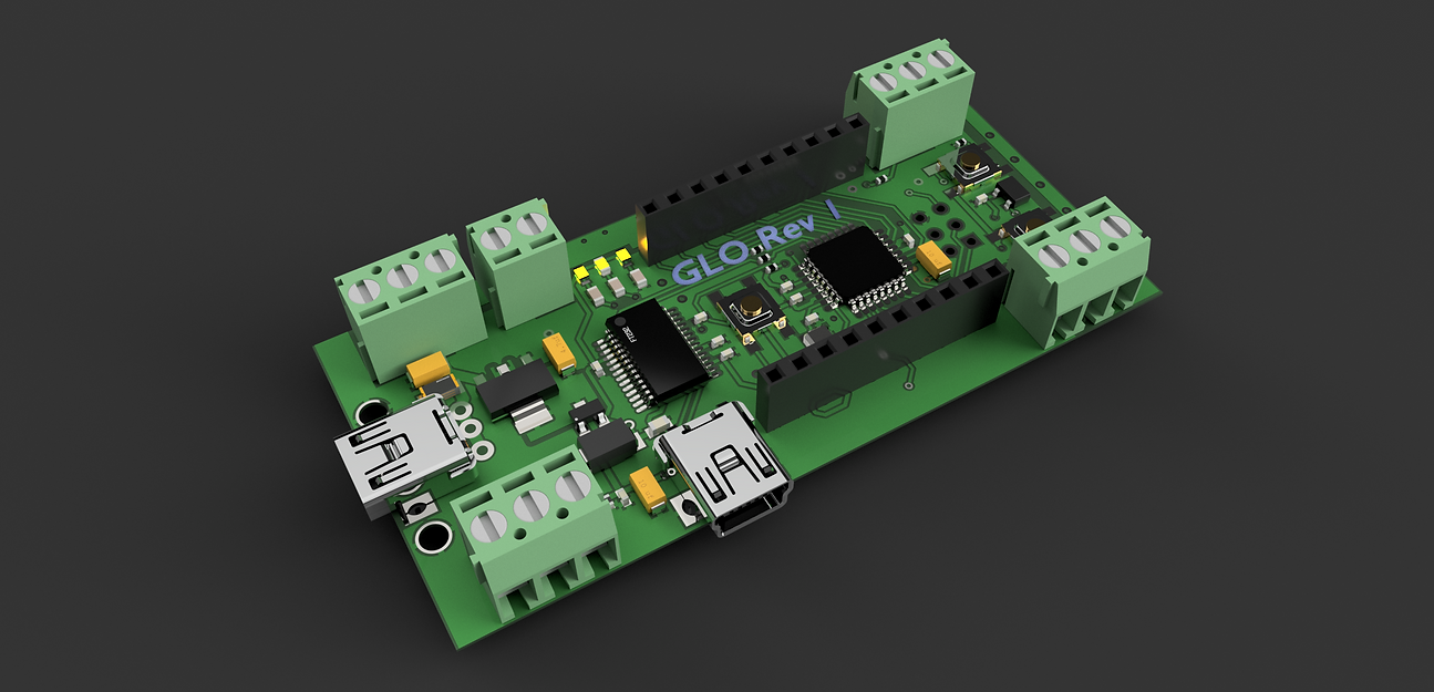
Glo
Rev 1
To Kickstarter Backers: Thank you for supporting the development of Glo! I sincerely appreciate it. If you have any feedback for this device or this website, such as new features to add or extra tutorials, fill out the form below or contact me via anavekar.om@gmail.com. Thanks again!
A hackable, Arduino-Based LED Strip Driver
With LED technology and DIY Electronics being more available to everyone with each passing year, we want to create a simple, sleek, and low-cost solution to control LEDs and Addressable LED Strips. Furthermore, unlike other LED controllers, we want to create a solution that allows users to create their own patterns and effects.
For more information regarding this project's Kickstarter page, please click here


atmega328p processor
A widely-used processor commonly used on the Arduino UNO, Nano, and Pro Mini. This chip is optimized for hobbyists and students due to its low cost and large user-community.


FT232 USB to Serial Converter
Glo contains an official FTDI USB-UART IC commonly found on the Arduino UNO and Nano. Allows for plug and play use and prevents communication errors caused by non-official chips.
Pinouts and Io

LED Channel 1 (D6)
LED Channel 4 (D9)
LED Channel 2 (D7)
LED Channel 3 (D8)
Power Terminal
Buttons (Wired to D4 & D5)
Hall Effect Sensor (Wired to D3)
ICSP Port (to burn bootloader)
Power Port

Program Port
Important Connection Information
-
DO NOT connect Glo's USB power port and its Power Terminal to a voltage source at the same time. This may damage the controller as well as both power supplies.
-
Glo has a feature in which it can be programmed while power is supplied through its USB power port or Power Terminal. This allows you to test LED patterns without having to unplug your power source.
-
If you are powering Glo via the Power Terminal (2 pin green connector) when programming the device, connect your computer's USB cable to the PROGRAM PORT ONLY
-
Connecting your computer's USB to the power port will result in a dual voltage source and could damage your computer's USB port, as well as the controller.
-
All ports and their pinouts have been marked on the underside of the PCB.
-
-
Please connect your LED strips and power supplies based on the pinouts given on the underside of the board. Incorrect wiring may lead to LED damage or failure.
FAQ
-
How do I connect Glo to an LED strip?To connect an LED strip to Glo's LED channels, follow the pinout marked on the bottom of the board. VCC -> 5V DIN -> DI GND -> GND Many LED strips have lead wires attached to them, which can be stripped and connected to the screw terminal. If these wires are not present/the LED strip was cut from another, lead wires can be soldered to the contact pads on the strip.
-
How do I upload code?To upload code to Glo: 1) Connect a Mini-USB cable from your computer to Glo's Program Port. 2) Run Arduino IDE and open code file. 3) Go to and select Arduino UNO/Genuino Uno or equivalent. 4) Go to Tools > Port and select the correct serial port (usually called usbserialXXXXXX). 5) Click Upload on the IDE, and wait till upload is completed.
-
Whats included in my Glo order?Glo will ship with the number of Glo units you back. Glo does not ship with LED strips or USB cables. If you are looking for LED strips, Adafruit's Neopixel strips are a good choice. The link is below: https://www.adafruit.com/product/1138?length=1
-
Glo is not recognized by my computer! What do I do?1) Make sure the Power LED (marked ON) is lit up when Glo is connected to its USB program port. 2) Make sure that the USB cable is connected to Glo's Program Port and not its Power port (only Program Port has a USB interface). Sidenote: Sometimes USB 3.0 ports have trouble communicating to Arduinos, so avoid them if possible. 3) Check if the USB cable you are using has data wires. Many mini/micro USB cables do not have data wires and are meant for power only. Try using a different cable and see if it works. 4) Disconnect any extra wires/LED strips that are connected. There may be a misplaced wire which is causing a short-circuit/communication problem 5) Press the RESET button (the button on the middle of the board) repeatedly. 6) Disconnect and reconnect the USB cable and check if a connection has been established. 7) Make sure your board and port is correct on the Arduino IDE (Board is Arduino UNO, and port should be something like usbserialXXXXXX). 8) Check your Arduino IDE version (we tested the boards with version 1.8.10. Sometimes newer versions can have trouble with non-Arduino manufactured boards). 9) Check if your computer may be blocking USB communication. This is more common on Windows machines. If you have a Windows device check your Device Manager to see if a port is detected there. 10) Install FT232 drivers to communicate with Glo's USB chip. This is usually not necessary but may solve the problem. The link is: http://www.ftdichip.com/FTDrivers.htm 11) Restart Arduino IDE and/or the computer. This may make the serial port visible. Keeping bugs and errors in mind, we designed Glo with a processor and USB communication chip that have massive community usage and have several documentation resources available. To learn more/troubleshoot further, please consult the link below: https://www.arduino.cc/en/guide/troubleshooting#toc1
-
How to fix flickering LEDs/glitchy patterns?Often this issue has three root causes: 1) Loose wire connection 2) Incorrect/bugged code implementation 3) Current/Voltage overload or short circuit To solve this problem: 1) Check all connections! Make sure 5V goes to 5V, GND goes to GND, and DIN goes to DIN. Most times, DOUT is accidentally connected to DIN port, causing problems. 2) Make sure the power supply is adequate for the task. Glo (and most LED strips) require 5V to run properly. Higher or lower voltages may cause board failure or other damage. Additionally, make sure that the power supply can provide enough current to run the LEDs. An easy way to see if the board is struggling is by looking at the ON LED. If it is flickering/ blinking randomly, Glo is not recieving proper power! 3) Check all code thoroughly. Usually, one mistyped integer or incorrectly contructed for-loop is all that is between success and failure!